This project is an implementation of Lab 1 from the Object class for ATLAS at CU Boulder. The purpose of this lab is to learn about simple circuits, custom made switches, and conductive materials.
Overall Objectives
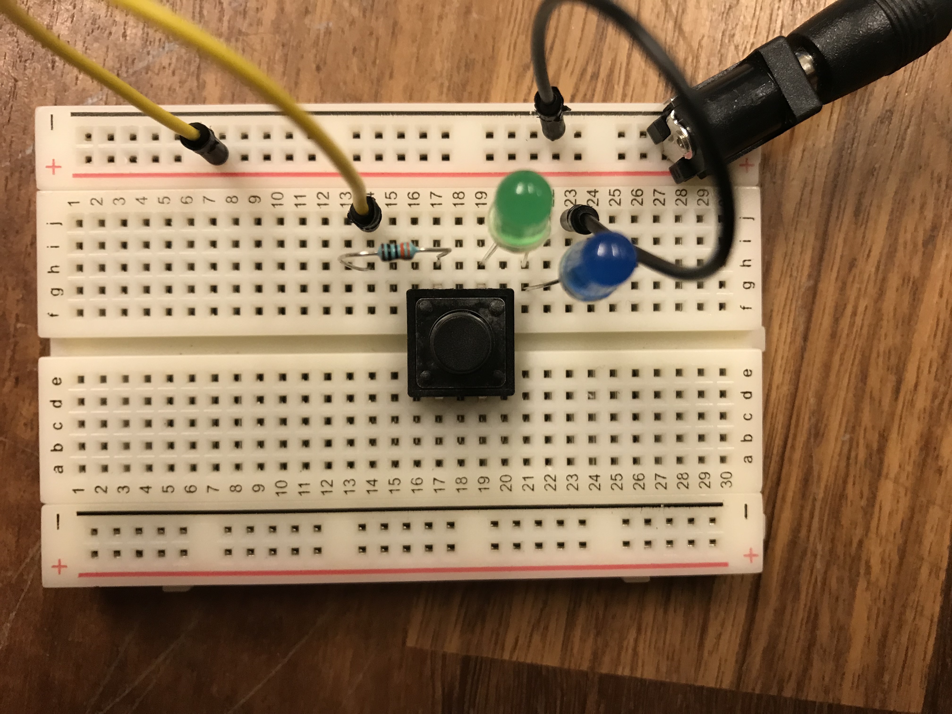
- Learn to build circuits on a breadboard
- Understand the difference between components in series and components in parallel Craft a custom switch
- Build a creative enclosure
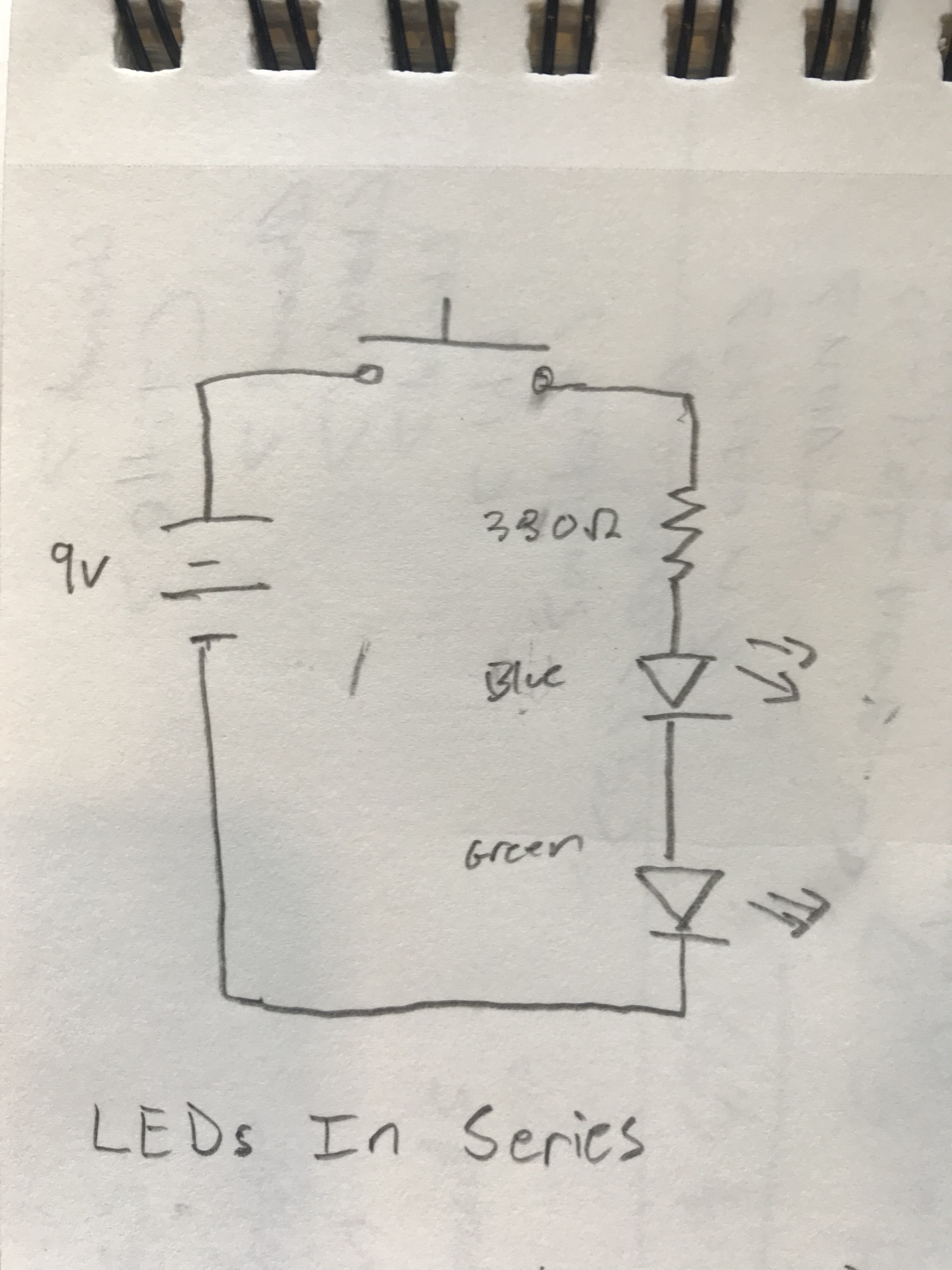
Part 1: LEDs in Series and Parallel
Objective
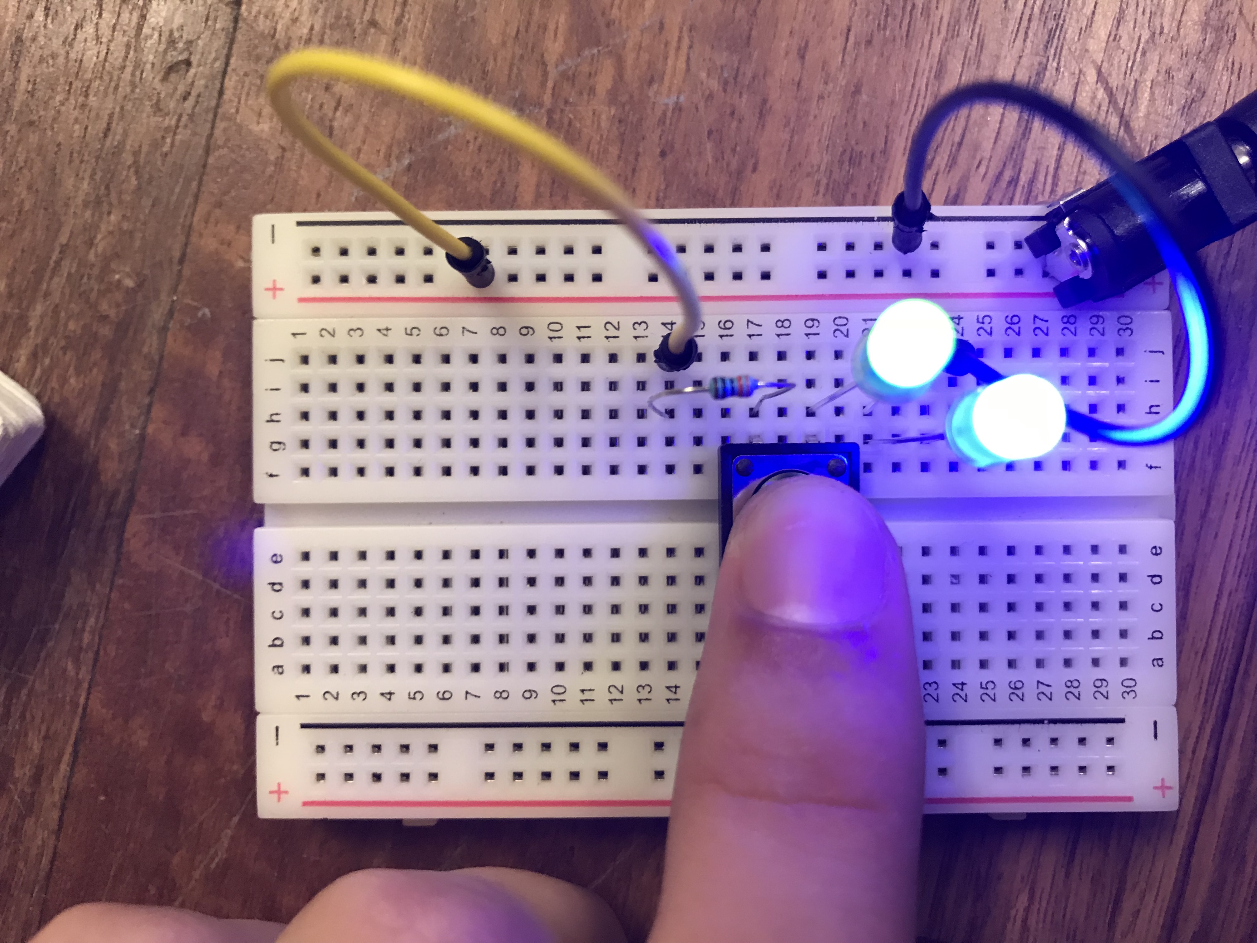
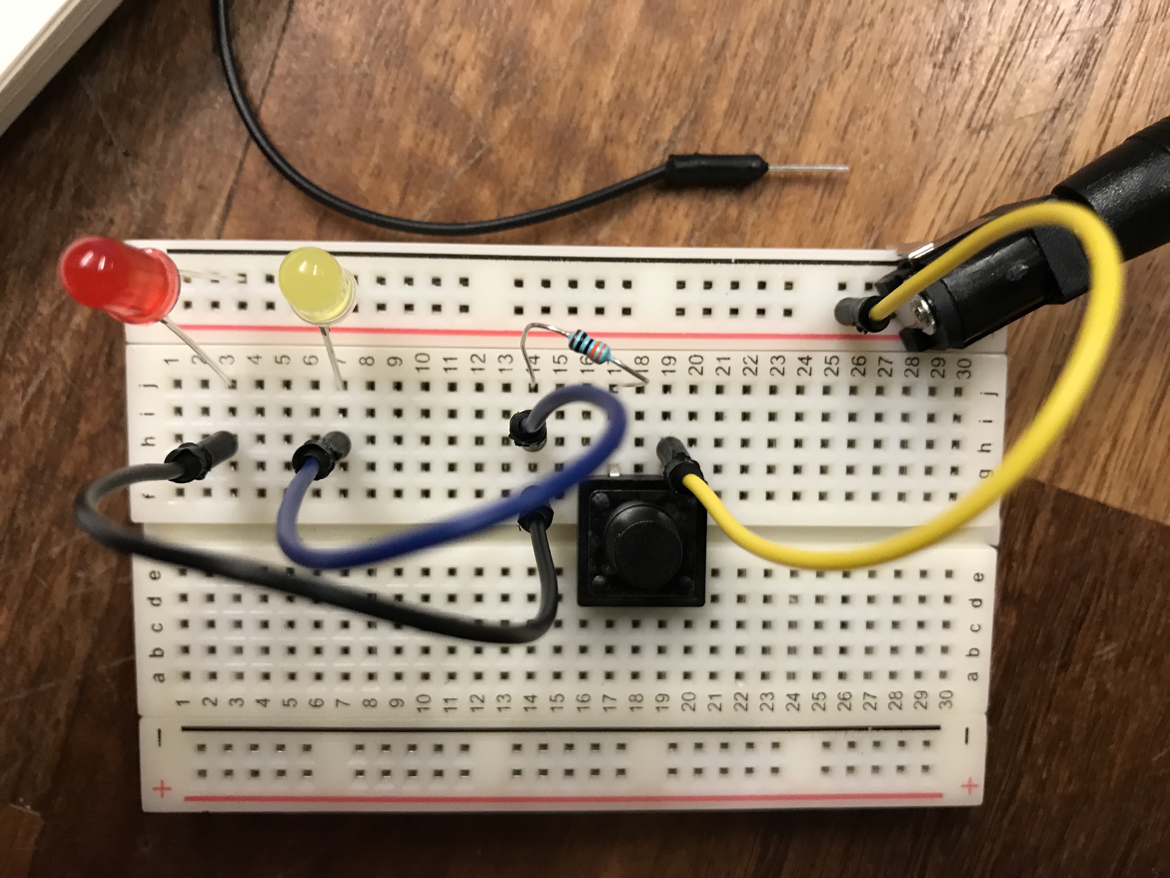
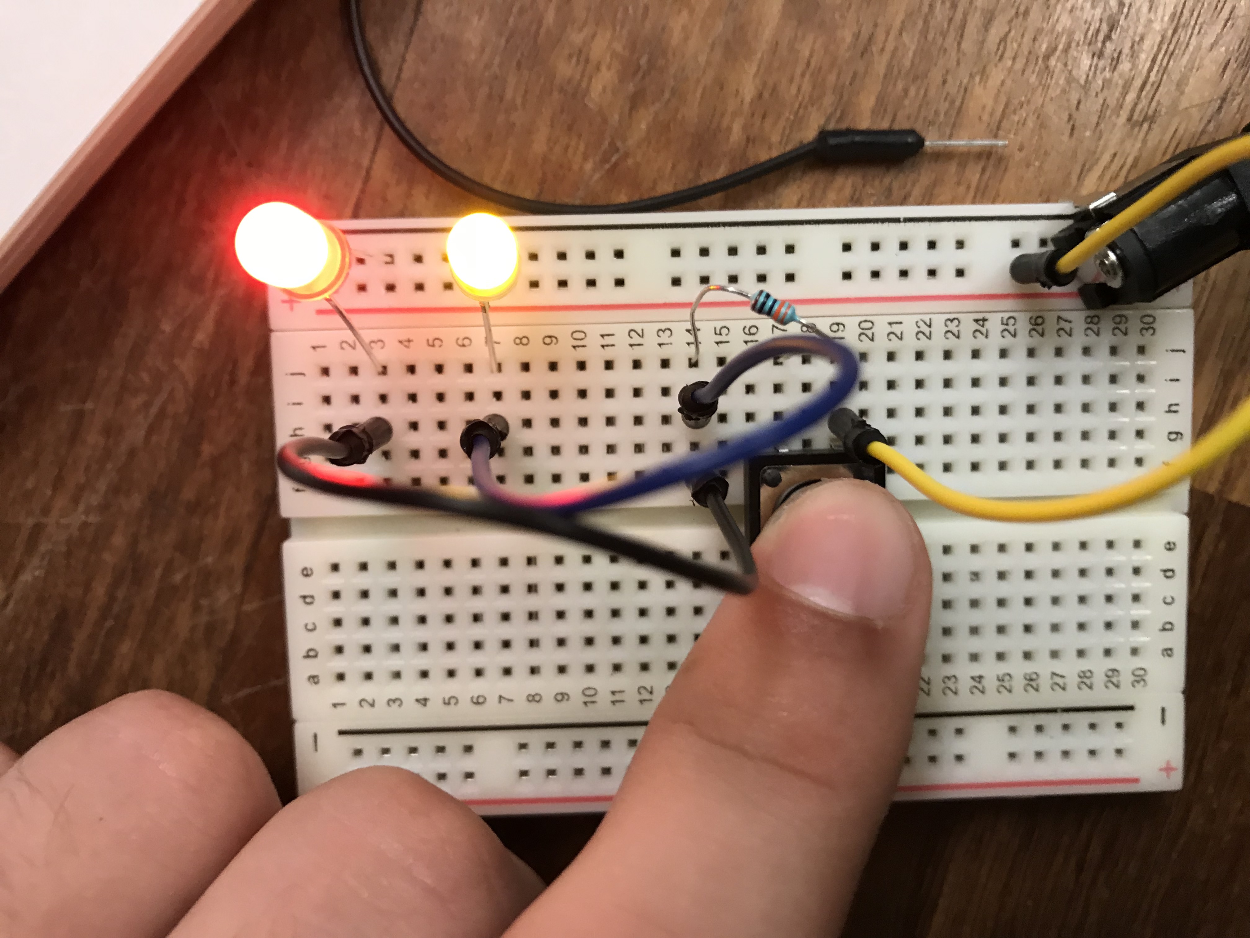
Create two LED circuits with a switch. The first circuit should have LEDs in series and the second, LEDs in parallel.
Materials
- Breadboard
- Assorted LEDs
- Jumper Wires
- 9V DC power supply
- Barrel Jack Connector
- 330Ω Resistors
- Momentary Switch
LED Specifications
| LED | Voltage (V) | Current (mA) |
|---|---|---|
| Red | 1.8 - 2.2 | 20 |
| Yellow | 2.0 - 2.4 | 20 |
| Blue/Green | 5 | 30 |
LEDs in Series
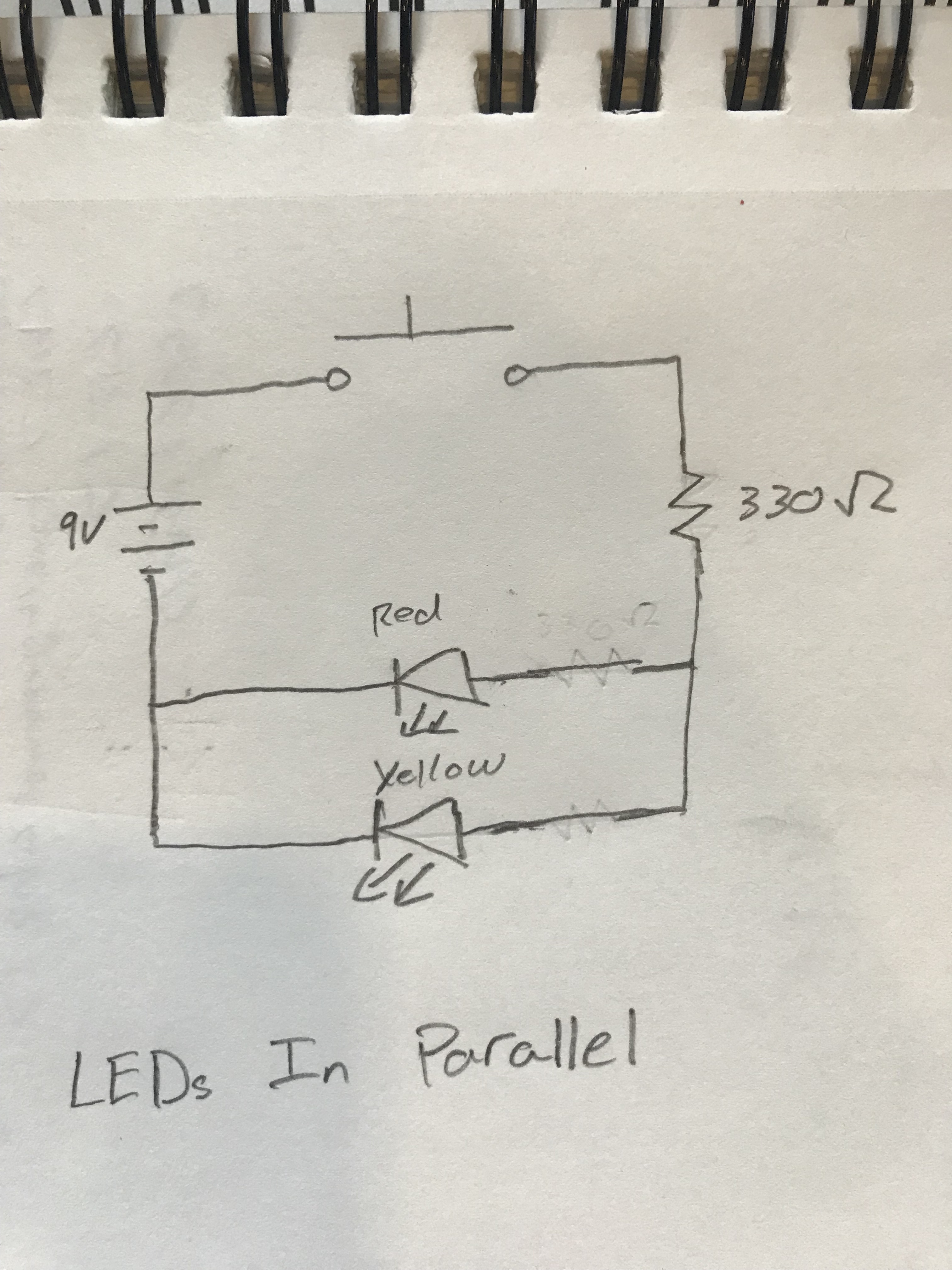
LEDs in Parallel
Parts 2 & 3: DIY Switch and Creative Enclosure
For my switch I made an origami fortune teller with LEDs. Different LEDs light up depending on the orientation of the origami. Here is a schematic of the circuit required for this project.
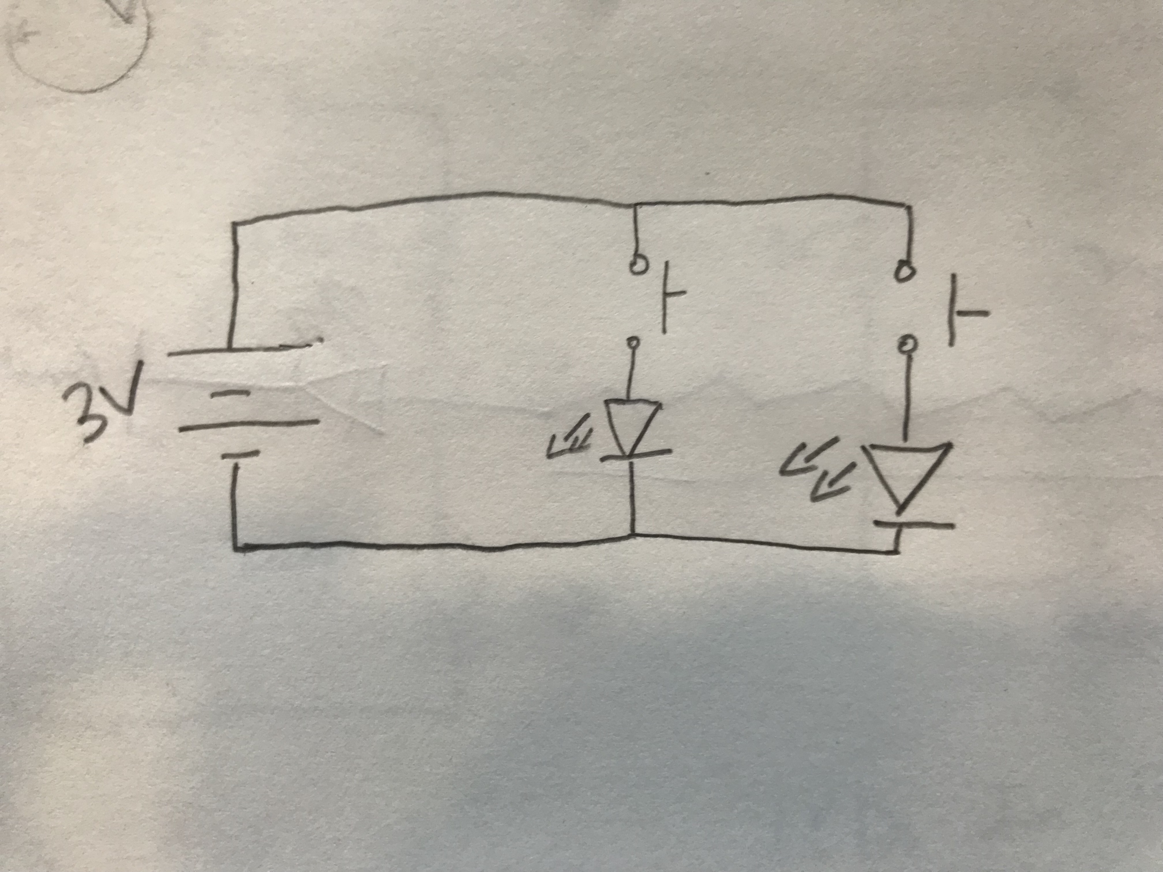
The circuit is very similar to the parallel LED ciruit created before. However, this circuit uses two switches - one for each LED.
Materials
- Paper
- Blue and Green LED
- Conductive Copper Tape
- Regular Tape
- 3V Coin Battery
Procuedure
- First I created a paper fortune teller. I won’t describe how to do this here. Just think back to 3rd grade (or find a tutorial online).
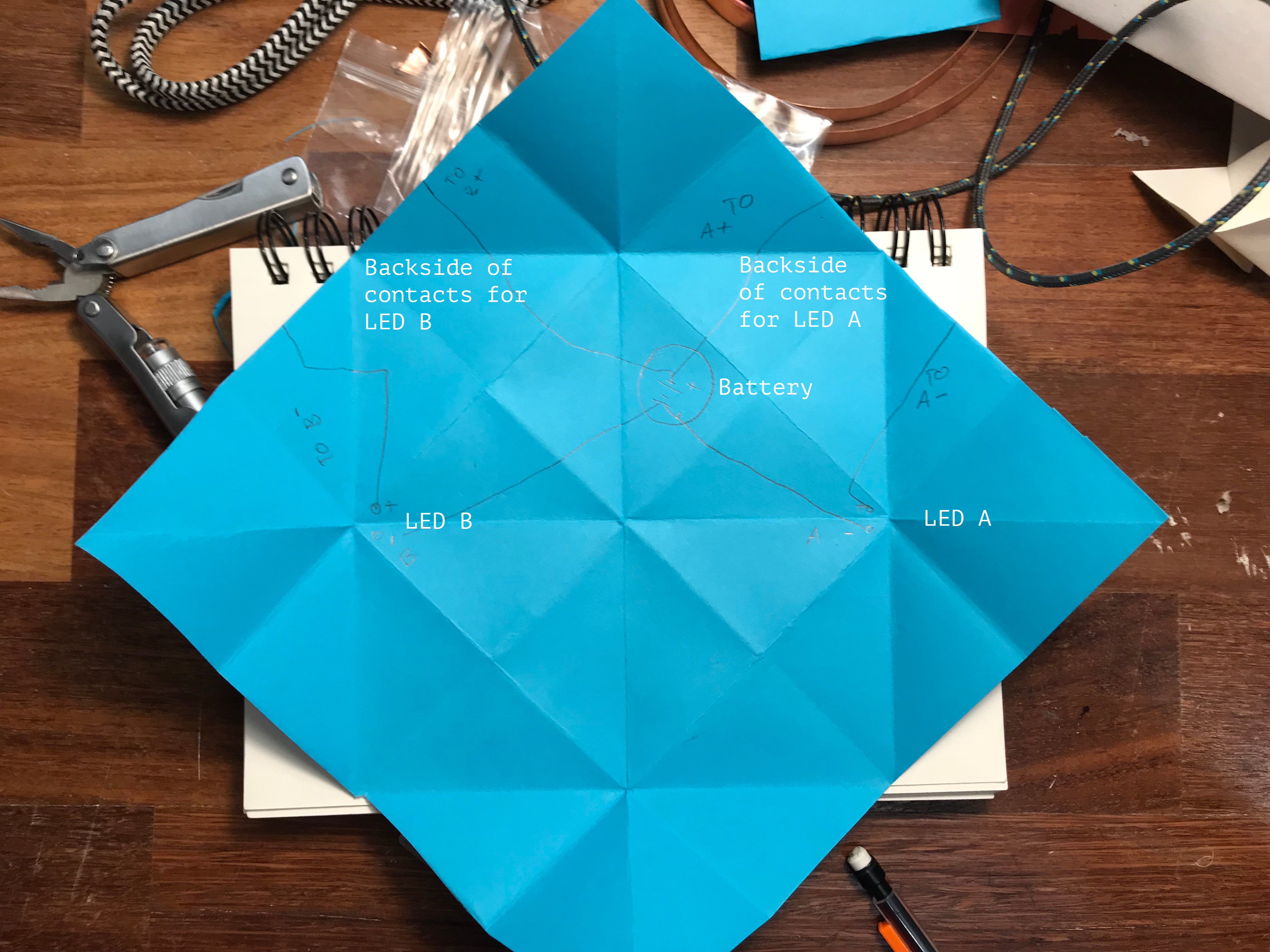
- Next, I unfolded the paper fortune teller and drew the circuit directly on the paper. This way, I could create the circuit without worring about keeping the origami together.
-
Watch out for the creases in the paper. Copper tape can run over these creases but harder materials (bateries, LED leads) cannot or they will prevent the paper from folding correctly. The leads of the LEDs poke through the back of the paper so they can be connected to the battery.
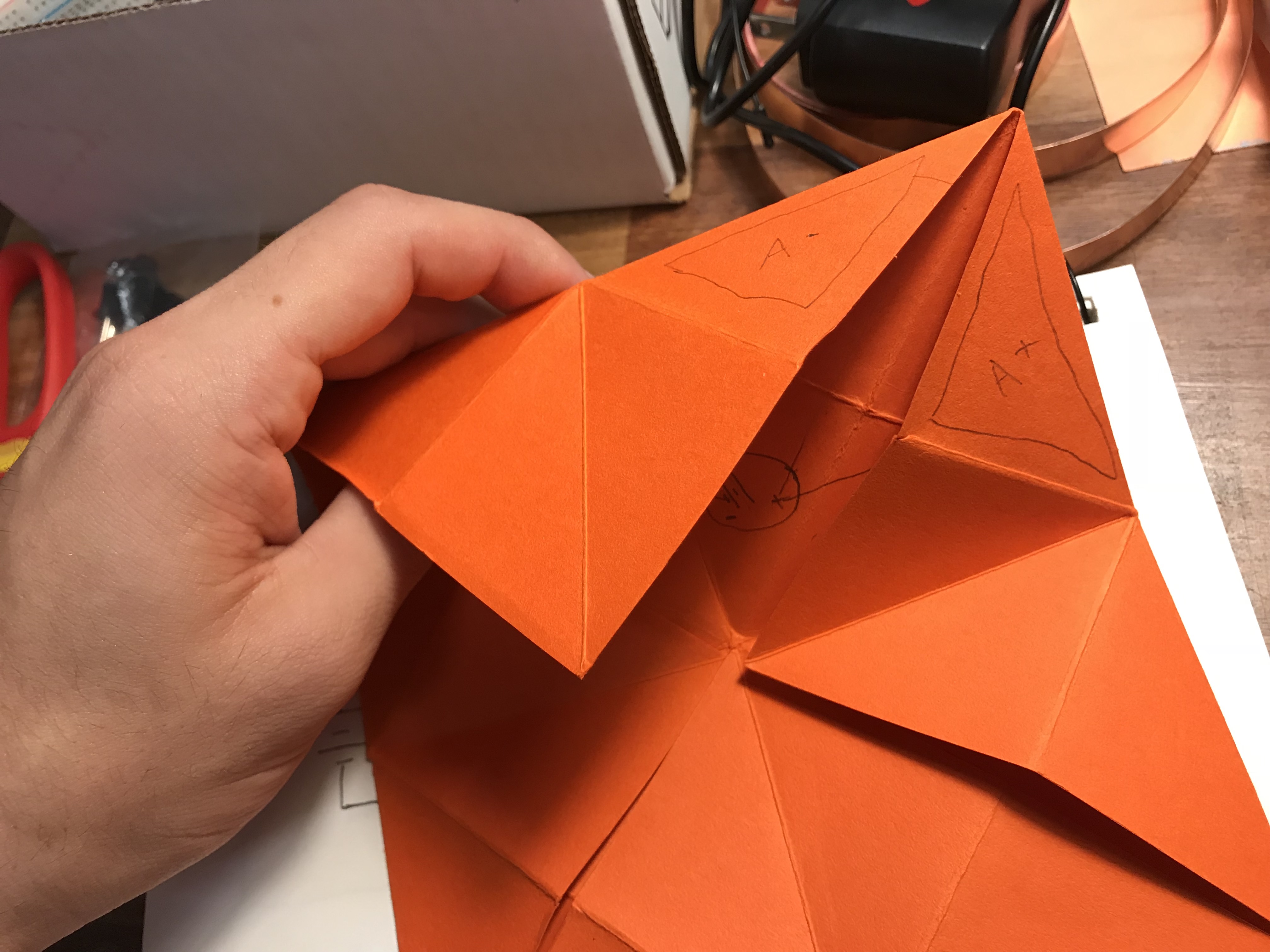
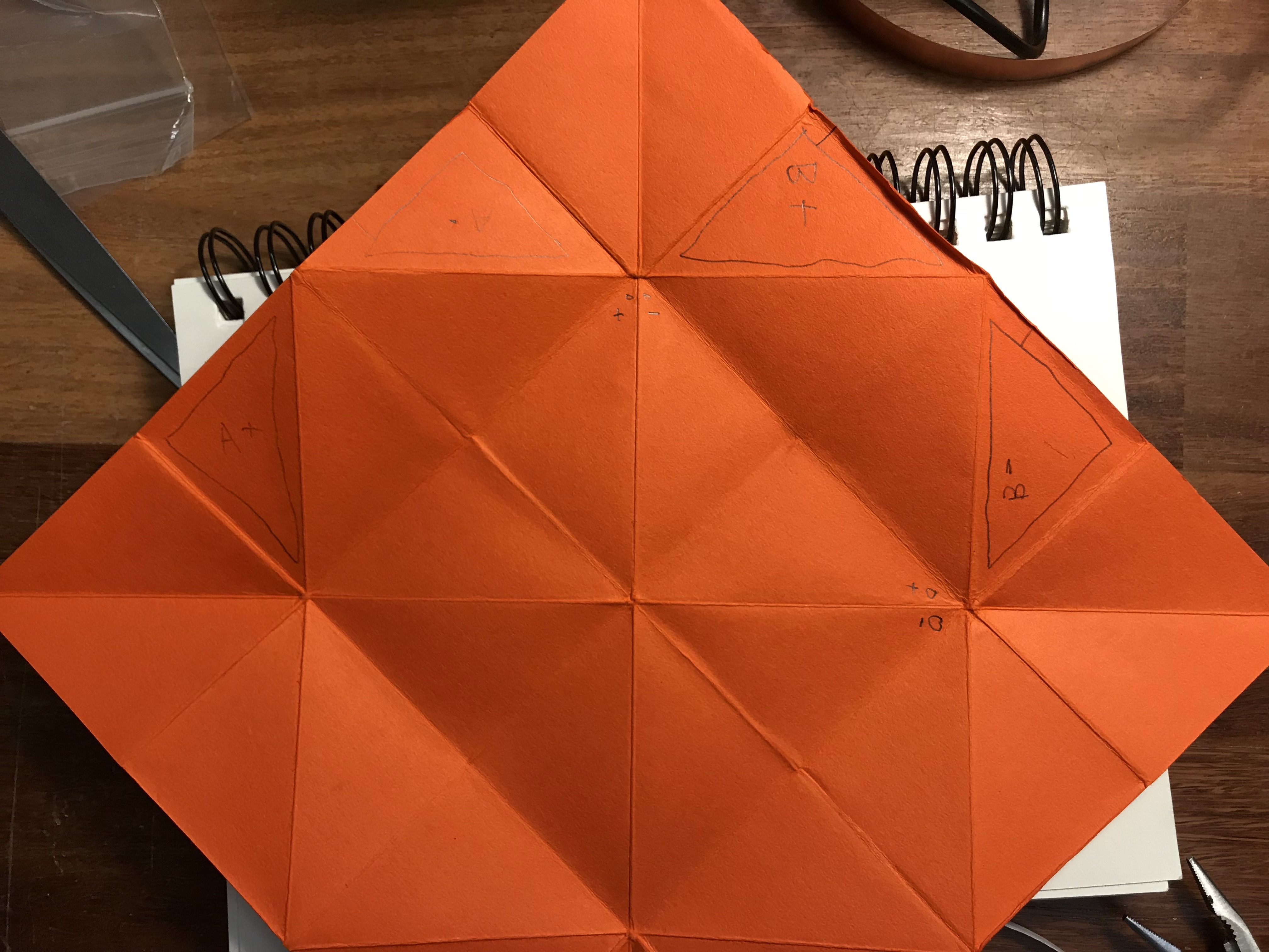
- This orange layout is a bit different from the final product but it demonstrates how I drew the components on the outside of the origami.
- After experimenting with a few circuit layouts, I put the components down on the paper.
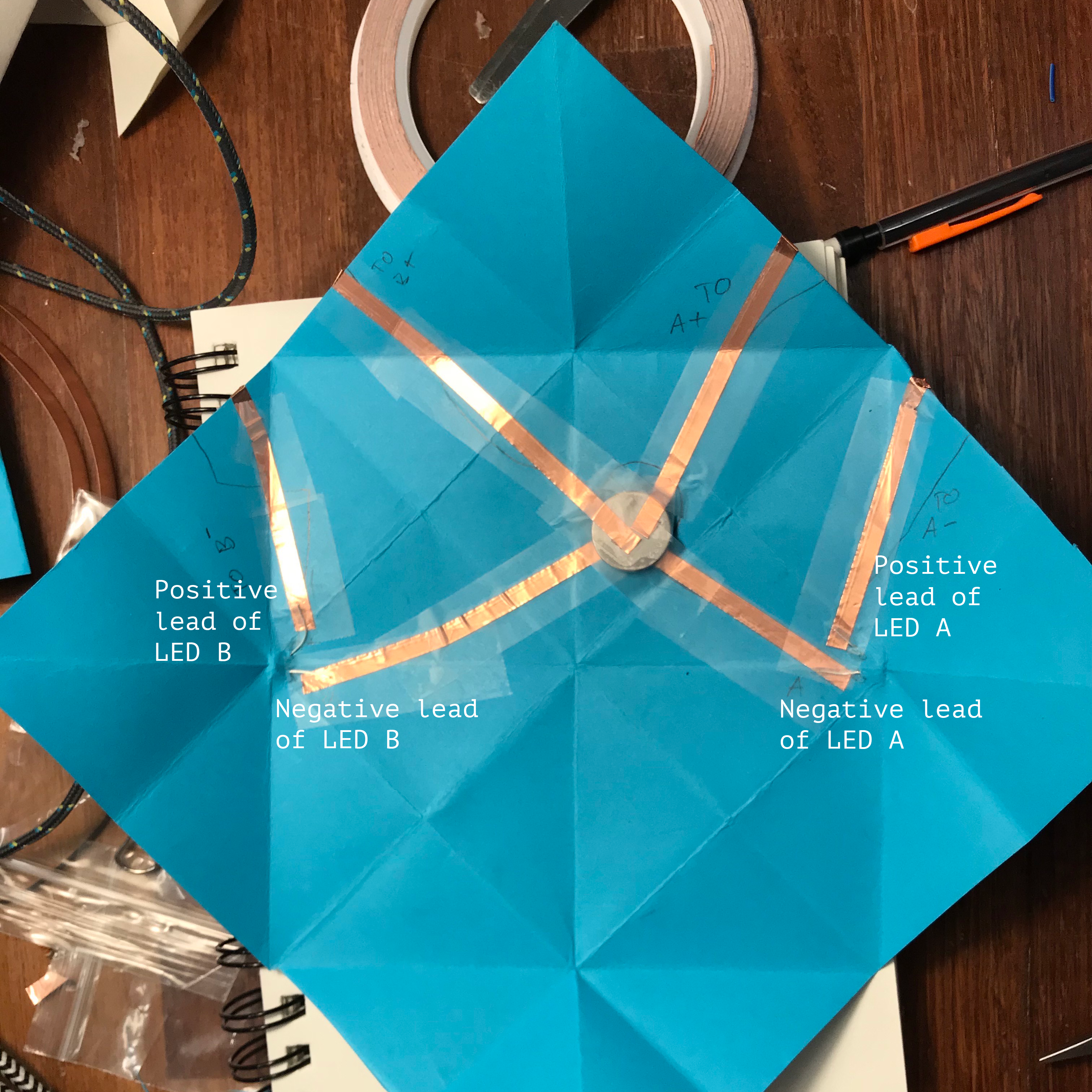
- The copper tape carries current from the positive terminal of the battery (top), through each of the contacts (also made of copper tape), throught the LED and finally back to the ground terminal of the battery (bottom). I used regular scotch tape both as insulation and to keep my components in place.
- One complication I ran into was with keeping the battery in contact with the copper tape. I had a hard time getting the battery to stick to anything. The circuit worked great when lying flat on the table, but when I folded it up the battery would slip out of place. I tried scotch tape, hot glue and even tried soldering the tape to the battery. I ended up placing the copper tape in the appropriate places above and below the battery and tightly wraping the “sandwich” with regular tape. This took a few tries.