This project is an implementation of Lab 2 from the Object class for ATLAS at CU Boulder. The purpose of this project is to explore digital inputs and outputs using a microcontroller.
Lab Requirements:
- Get set up with the Arduino environment
- Build a circuit with one digital input (a switch) and two digital outputs (LEDs)
- Program the Arduino to power the LEDs based on the switch state
- Laser cut a project enclosure
Part 1: Build the Circuit
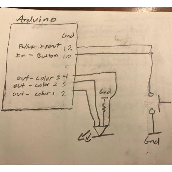
This project uses two circuits. One for switch detection and one for controlling the LED. Pin 12 on the Arduino is set to INPUT_PULLUP meaning that it uses the microcontroller’s internal resistor to prevent a short circuit. Pin 10 is set to INPUT and detects the state of the push-button.
The second circuit is for the led. Pins 2, 3, and 4 are set to OUTPUT and send 5V each to the pins on the LED.
Part 2: Programming the Microcontroller
Every time a user pushes the button, the LED changes colors. This functionality is made possible by programming the microcontroller to change states every time a button press is detected. The code is provided below:
#define PRESSED LOW
#define LED1 2
#define LED2 3
#define LED3 4
#define BUTT_IN 10
#define PULLUP_INPUT 12

bool lastButtonState = 0;
int currentColor = 0;

void setup() {
  // put your setup code here, to run once:
  Serial.begin(9600);
  pinMode(PULLUP_INPUT, INPUT_PULLUP);
  pinMode(BUTT_IN, INPUT);
  pinMode(LED1, OUTPUT);
  pinMode(LED2, OUTPUT);
  pinMode(LED3, OUTPUT);
}

void loop() {
  // put your main code here, to run repeatedly:
  digitalWrite(LED1, LOW);
  digitalWrite(LED2, LOW);
  digitalWrite(LED3, LOW);

  bool buttonState = digitalRead(BUTT_IN);

  if (buttonState != lastButtonState) {
    Serial.println(buttonState);
    lastButtonState = buttonState;

    if (buttonState == PRESSED)
      currentColor = (currentColor + 1) % 4;
  }

  switch(currentColor) {
    case 0:
      digitalWrite(LED1, HIGH);
      break;
    case 1:
      digitalWrite(LED2, HIGH);
      break;
    case 2:
      digitalWrite(LED3, HIGH);
      break;
    case 3:
      digitalWrite(LED1, HIGH);
      digitalWrite(LED3, HIGH);
      break;
  }

}
Part 3: Laser cut an enclosure
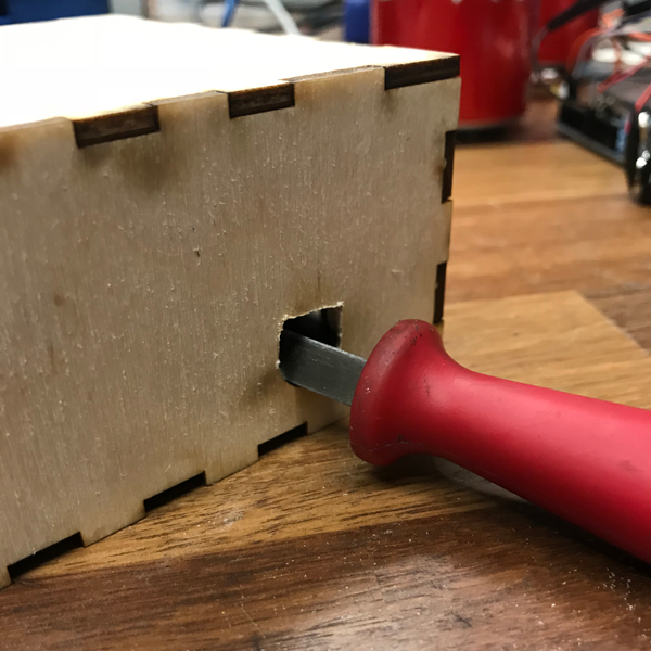
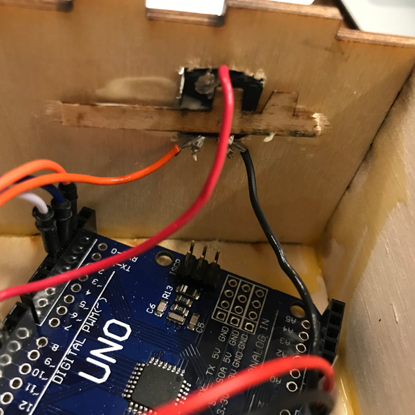
For my enclosure, I decided to make a box with a personal logo on it. The box features an L and terminal prompt because of my passion for programming. I made the design in Adobe Illustrator with the help of MakerCase. I made my original design with circle hole for the button but it didn’t fit. I ended up using a filing tool to make the hole into the shape of a square so that my button would fit. I then used a thin strip of wood and some wood glue to hold the button in place.
Thanks for reading!
— Lucas