Purpose and Audience
The main purpose of this project was to learn about new concepts including arduino audio, digital audio synthesis and capacitive touch sensing. The aim of the product was to be a basic synthesizer for musicians such as myself.
Materials
- Arduino MKR Zero
- I2S 3W Class D Amplifier Breakout - MAX98357A (https://www.adafruit.com/product/3006)
- mini SD Card
- Protoboard
- copper tape
- wire (preferably flexible/stranded)
- 4Ω 3 Watt Speaker
- 1inch thick wood
- wood glue
Resources
- Arduino theremin example - https://create.arduino.cc/projecthub/Arduino_Genuino/i2s-theremin-cec47a
- Arduino i2s tone example - https://www.arduino.cc/en/Tutorial/I2SSimpleTone
- I2S Amplifier breakout guide - https://learn.adafruit.com/adafruit-max98357-i2s-class-d-mono-amp/overview
- Arduino SD Library - https://www.arduino.cc/en/Reference/SDCardNotes
- Arduino I2S sound library - https://www.arduino.cc/en/Reference/ArduinoSound
- Arduino CapSense library - https://playground.arduino.cc/Main/CapacitiveSensor?from=Main.CapSense
Summary
This project has two main components. Input detection, which uses the capacitive touch sensors, and sound generation.
Input detection
The Arduino capsense library uses two pins for one sensor – a send pin and a receive pin. The sensor can be any conductive material. I chose to use copper tape for the aesthetic. Either end of the sensor is connected to the send and receive pins. The library works by outputting a voltage on the send pin and calculating how long it takes for the receive pin to change to the same state. Placing a capacitor in between the pins will cause the state change to take longer. Here’s the cool part: your body can act as a capacitor. So when you touch the copper tape (the sensor) the library will detect the change in the circuit and notify the program that the sensor has been touched. A resistor needs to be placed in series with the receive pin and the sensor. The value of the resistor depends on how sensitive you want the sensor to be. I used a 1MΩ resistor. Smaller values can make the sensors act as proximity sensors.
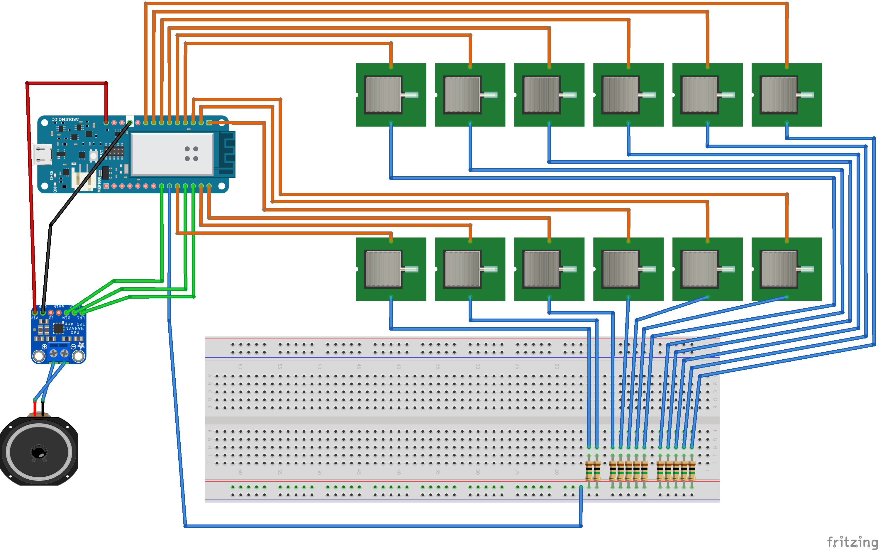
Detecting multiple sensors individually can be more complex. Only one send pin is needed, but each sensor needs it’s own receive pin in order to discern between sensors. Each sensor needs a resistor in series with the receive pin. For my circuit, I connected each of the resistors in parallel to the send pin. Each resistor connected to one end of the copper tape. The other end of the copper tape connected to the sensors corresponding receive pin. You can find the layout in my final schematic below. Each sensor must be wired precisely in order to avoid noise. If there is too much noise between connections, the program will not be able to detect individual sensors accurately.
Audio
My original plan was to create sound waves using mathematic principles of audio wave synthesis. This code would involve calculating discrete amplitudes of a basic waveform (sine, square, triangle, saw) and outputting these values according to a specified frequency (pitch) and sample rate. These amplitude values (samples) can be outputted to the external DAC (the MAX98357A) using the I2S library. One of the main difficulties with this method is that the samples need to be generated consistently at a specific rate (44.1 kHz, ideally) or else the resulting audio will have pops or incorrect pitch. This can be done with timers but that means that the timers can’t be used for anything else – like the touch sensors.
Enclosure
My enclosure is a simple wooden box with a hole for the speaker and small slits for connections to the copper tape. I designed the box using illustrator and makerbox.com. I’m very happy with the look of the box, however I wish I could have added more components.
Setbacks
Each of my main components worked individually. However, results were poor when combining them together. Sensors were slow to detect and the audio rate was inconsistent. My suspicion was that both the I2S library and the CapSense library were trying to use the same internal timer and this caused unwanted side effects.
Final implementation
Due to setbacks, I decided to take an easier route and generate sound by playing back pre-recorded samples with the ArduinoSound library. The sounds were recorded digitally from a software synthesizer on my laptop. Unfortunately, my external DAC (the MAX98357A) was broken and could not produce sound without loud noise. Another problem I ran into was that the CapSense library could not detect input while sound was playing. This meant that I could not stop the sound when the user lifted their finger or pressed a different note. In addition, wiring 12 capacitive sensors on a small protoboard proved to be pretty difficult. I ended up disabling some of the sensors because they were creating or receiving too much noise from surrounding sensors.
Schematic
Code
Find the code on Github: https://github.com/LucasDachman/waveplay
Photos and Video


Future Directions
My initial prototype with five sensors used 1MΩ resistors but the set of 12 sensors may have needed bigger ones. Other solutions could include trying to insulate the sensors with tape or plastic or using material other than copper. Using recorded audio samples makes the project more of a keyboard than a synthesizer. In the future, I’d like to get the actual synthesis part working. In that case I’d be able to add other components to modulate the shape and tone of the sound. Since this process is extremely time sensitive, it might be better suited for a multiprocessing device like a Raspberry Pi. That being said, I’m sure complex audio synthesis could be achieved with more precise coding strategies and advanced use of timers.